Last update - 6/28/2010
A WhiteStd.Up/Dn recalibration should be done outside on a clear day.
If the radiometer has any bands 1100 nm or higher, allow at least fifteen minutes for the radiometer to adjust to the outside temperature.
To perform a WhiteStd.Up/Dn MSR Calibration, do the following:
1) Bring up the MSR MAIN MENU.
         MSR MAIN MENU
 1 Config-Status
 2 ReConfigure     7 Memory Card
 3 Retrieve Data   8 MSR Program
 4 Clear Data      9 Exit MENU
 5 View           10 BYE
Enter Selection/Command
*2
|
2) Type 2 and press Enter to display the RECONFIGURE MSR menu.
       RECONFIGURE MSR
1 Date  6 Location 11 Calibrate
2 Time  7 Record   12 Power-Off
3 SS    8 Samples  13 Mode
4 Rem   9 GMT Difference
5 ID   10 IRR       M Main Menu
Enter Selection/Command
*11
|
3) Type 11 and press Enter to display the CALIBRATION COEFFICIENTS menu.
CALIBRATION COEFFICIENTS 1 Enter Calibration 2 Display Calibration 3 Recalibrate M Menu Enter Selection/Command *3 |
4) Type 3 and press Enter to display the RECALIBRATION menu.
RECALIBRATION 1 IRR 2 Two-Point 4 White-Standard Up & Down M Menu Enter Selection/Command *4 |
5) Type 4 and press Enter to begin the MSR WhiteStd.Up/Dn recalibration.
CALIBRATION TO WHITE-STANDARD POSITION RADIOMETER OVER WHITE CARD (45 DEGREES TO SUN) PRESS ENTER WHEN READY |
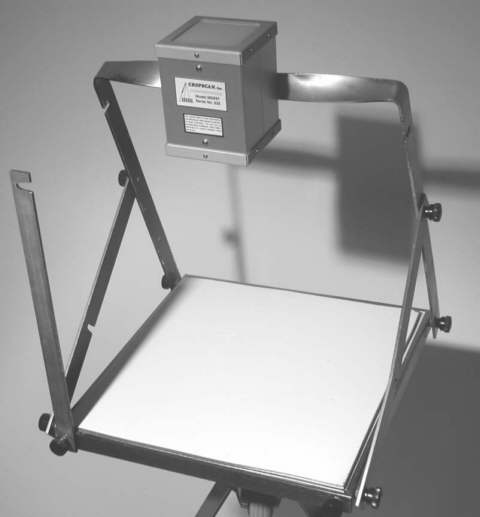
6) Position the white reference panel such that the sun is striking it at a 45 degree angle. In the following picture, a white reference panel is mounted on a triplod platform. A bar, mounted at a right angle to the platform casts a shadow and the platform is positioned so the end of the shadow is cast to a scribed line representing a 45 shadow angle. After the platform positioning adjustment, the bar can be lowered out of the way.
Position the radiometer to point straight at the white panel surface (i.e.
perpendicular or nadir to it). In the picture below, the radiometer
mount holds the radiometer such that it is always facing perpendicular
to the platform surface, irregardless of the position of the platform
on the tripod.
(Note: For radiometers used in weather-proof enclosures,
typically for standalone arrangements, the radiometer should be left inside
the enclosure and the enclosure positioned over the white panel for this
calibration).
 |
|---|
Stand to the side and below the surface of the panel, if possible, to minimize reflections from your body/clothing striking the radiometer or platform.
Press Enter, as instructed above. The incoming irradiance readings are made by the up sensors and the white panel reflected irradiance readings are made by the down sensors at the same time.
PLACE BLACK CARD OVER TOP SURFACE PRESS ENTER WHEN READY |
7) Place the black card over the top surface of the radiometer, wait several seconds and then press Enter. The up sensors DarkmV readings are then taken.
PLACE BLACK CARD OVER BOTTOM PRESS ENTER WHEN READY |
8) Hold the black card up against the bottom surface of the radiometer, wait several seconds and then press Enter. The down sensors DarkmV readings are then taken.
Calculating... |
At this point the calibration constants are calculated and placed in the Calibration Constants table.
MSR Serial# (170): |
If the prompt for MSR Serial number appears (MSR5 and MSR87 radiometers) and your radiometer serial number appears in the parenthesis, just press Enter. If the correct serial number does not appear type the correct number and press Enter. This prompt will not appear for MSR16/MSR16R radiometers and it is required to have previously entered the MSR16 module serial numbers in the Calibration Constants table.
RECALIBRATION 1 IRR 2 2-Pt.Up/Dn 4 WhiteStd.Up/Dn M Menu Enter Selection/Command *M |
This completes the WhiteStd.Up/Dn recalibration. Enter the M option to return to the prior menus.
 CROPSCAN, Inc. Home Page
©2017 CROPSCAN, Inc.
all rights reserved